
Audio Equalizer Circuit
Design and creation of a multi-band audio equalizer circuit
Project Overview
Role
I was responsible for the full design, construction, and testing of a functional audio equalizer circuit.
Project Duration
Fall 2023 Semester
Key Skills
Circuit Design · Analog Filters (RC) · Op-Amps · Gain & Volume Control · Power Amplification · Troubleshooting
Tools/Software
Multisim · Keysight MSO-X 3014T Oscilloscope · LM324 & LM356 Op-Amps · RC Circuit Components
Project Description
The Challenge
The goal of this experiment was to design and build a multi-band audio equalizer circuit that met a series of specific constraints. Key objectives included implementing low-pass, mid-pass, and high-pass filters, each with independent volume controls, as well as a master volume control. The circuit also needed to achieve specific gain and voltage requirements, maintain a maximum ripple of 15 mVrms, and provide an output power greater than 400 mW.
The Approach
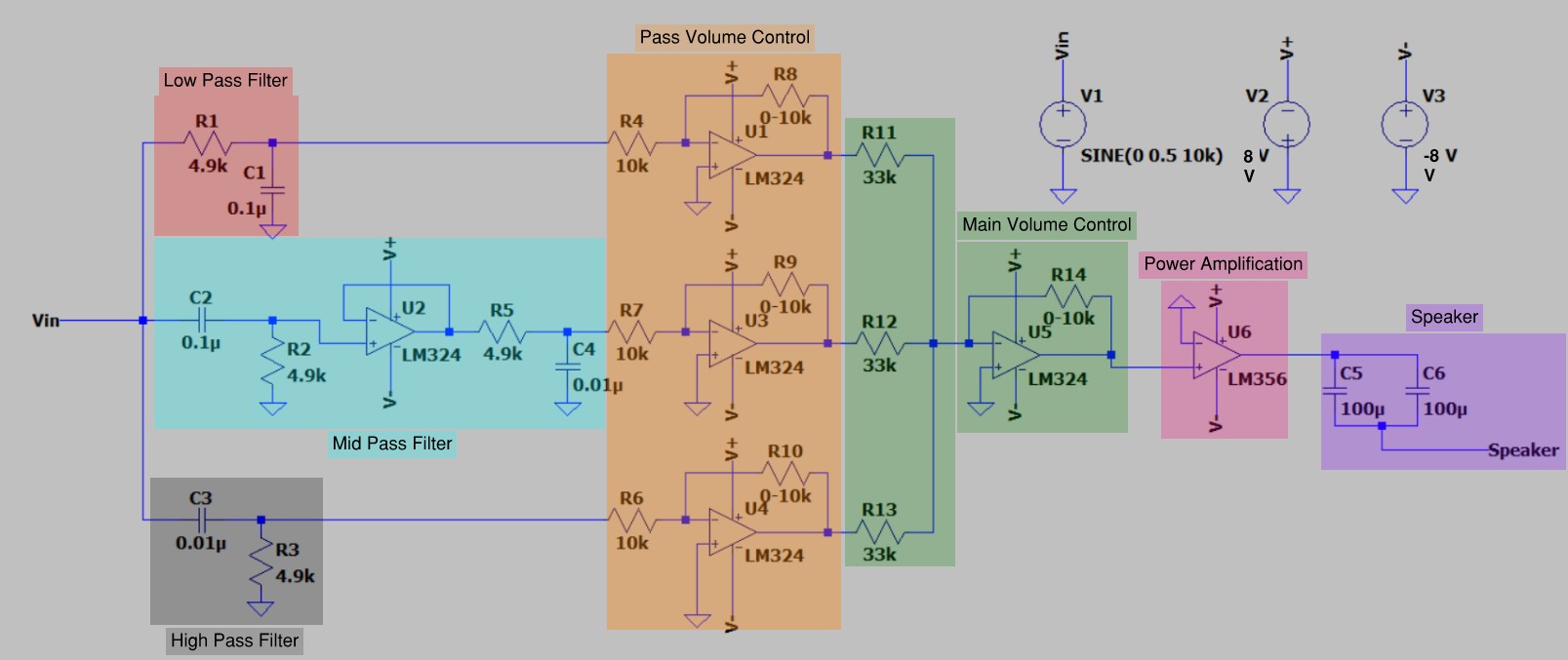
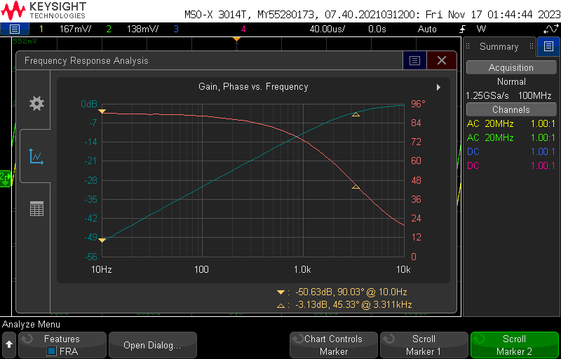
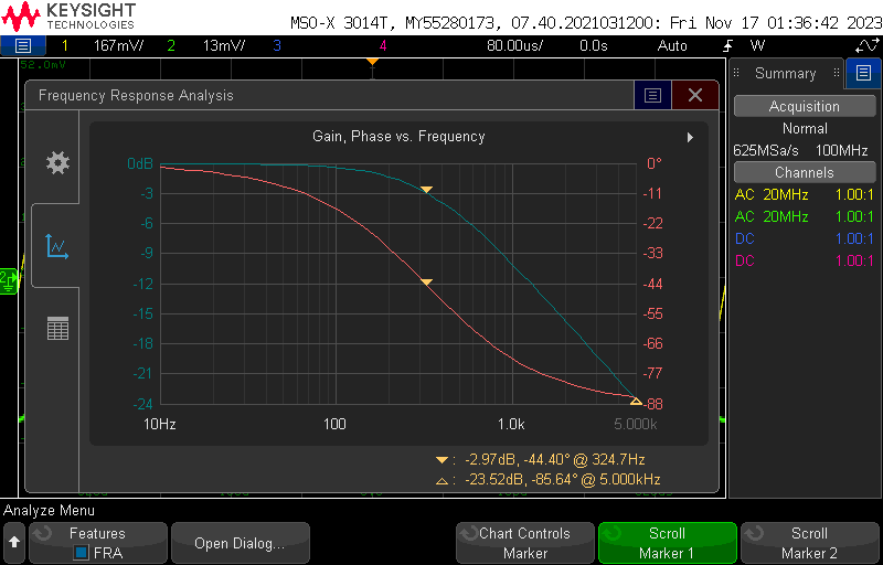
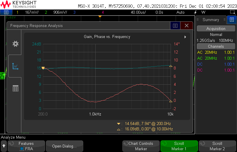
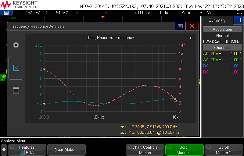
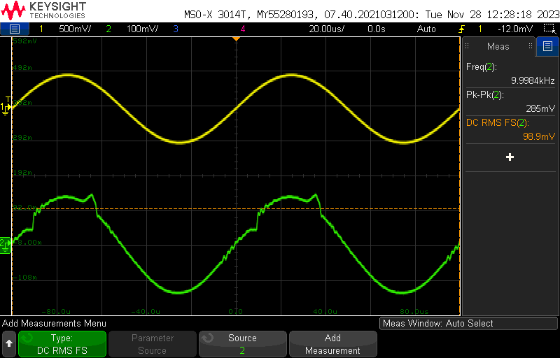
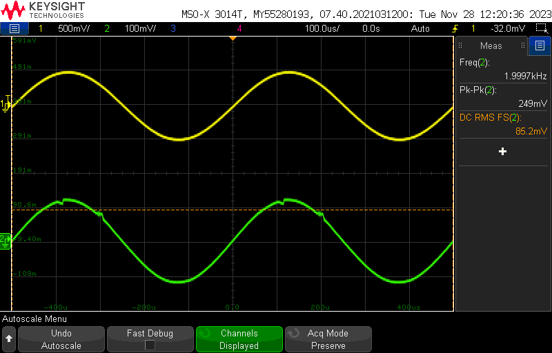
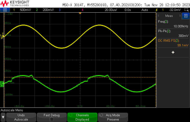
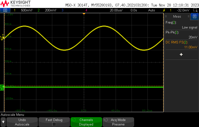
The approach involved breaking the complex circuit down into smaller, testable components. I first designed and constructed the individual filters: a low-pass filter with a cutoff at 320 Hz, a high-pass filter with a cutoff at 3200 Hz, and a mid-pass filter built by combining a high-pass and low-pass filter with a buffer in between. Each filter’s gain was then controlled using an inverting op-amp with a potentiometer to allow for adjustable volume. All the filtered signals were then fed into a summing amplifier for master volume control before being sent to a power amplifier to meet the output power requirement. I used a Keysight oscilloscope to perform frequency analyses and measure voltage values to ensure each component met the specified constraints.
The Outcome
Overall, the project was a success, with the final audio equalizer largely meeting its objectives. The frequency analysis showed that the filters’ cutoff frequencies were very close to the theoretical values, and the minimum volume settings were well within the required voltage limits. The circuit’s power amplifier also successfully delivered an output power greater than the 400 mW requirement. However, a key shortcoming was identified in the maximum voltage settings for the low-pass and mid-pass filters, which exceeded the 10% margin of error. This was likely due to the capacitor selection in the low-pass filter. Despite this minor error, the circuit’s overall performance was acceptable, and it successfully provided clear, adjustable audio.
Visual Showcase


Official Report
If you would like to review the full details of this project, you can download the complete report here:
